Glove boxes
Design and application
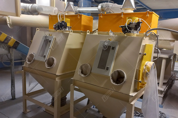
The unloading station is designed to perform operations for emptying polyethylene nonwoven bags from transported in them powdery and fine lumpy (up to 6 mm) materials and protects the operator from contact and inhalation of harmful and toxic substances. The debagging station in this configuration is not designed for operation in explosive areas.
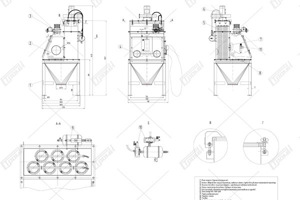
The unloading station comprises the following components:
– support frame with discharge hopper (pos. 1)
– hood featuring a bag loading door, service hatch, and empty bag removal port (pos. 2)
– disc shutter with protective cover and pneumatic control valve (pos. 3)
– ports equipped with gloves for handling hazardous materials (pos. 4)
– filter unit containing integrated filter bag regeneration tubes (pos. 5)
– fan positioned on the cover of the filter unit (pos. 6)
– separating panel with perforations to extract dusty air from the rasping zone (pos. 7)
– grids with a knife (pos. 8)
– receiver (pos. 9) housing with pneumatic valves (pos. 10) for filter regeneration mounted on it
– air preparation unit (pos. 11)
The support frame, along with the unloading hopper, serves as a vital structural component. It consists of a single-piece welded construction and is designed to securely hold the hood with the sack loading door. The discharge hopper is equipped with a grid (pos. 8) that incorporates a built-in knife for efficiently opening polyethylene bags. Additionally, the frame features holes in its feet for easy floor attachment. The delivery package of the discharge station includes clamps for connecting the outlet sleeve of the discharge hopper to the receiving hopper shell or any other compatible unit.
The hood, featuring a door, serves the purpose of safeguarding the working area during bag emptying operations. It is equipped with a filter unit, integrated filter regeneration pipes, a fan, and a receiver. Inside the hood, a lamp is installed to provide adequate illumination within the bag rasping zone. To facilitate maintenance and separation of different areas, the hood is structurally divided by a removable separating panel (pos. 7) into the bag rasping zone and the zone housing the filtering elements. At the upper part of the hood, a disk slide gate (pos. 3) is positioned to allow the inflow of external air into the bag separation station when the fan is activated.
For operator convenience and safety, two glove ports are situated on the front panel of the rasping station. These gloves are specifically designed to prevent direct contact between the operator's skin and the material being threshed after the bag has been opened.
The filter unit is positioned at the rear part of the hood and consists of a collection of filter bags mounted on a wire frame with a flange. This frame is securely attached to the hood head of the debagging station using a gasket. When replacing the filter bags, it is necessary to follow specific steps: first, remove the flexible pneumatic tubes from the cap of the mixing station head; then, tilt the cap with the fan on hinges at a 90° angle; subsequently, unscrew the nuts that secure the filter elements to the cap head; finally, take out the frame with the filter bag from the cap head. It is crucial to perform these tasks while ensuring personal protection for the skin, eyes, and respiratory system.
The fan is connected to the head cover of the station through a transition pipe. Its primary function is to extract the filtered air from the station cavity for further purification.
The receiver, along with pneumatic distributors and the air preparation unit, constitutes the pneumatic system of the debagging station. Their purpose is to facilitate the regeneration of the filter elements when they become clogged with debagged material. The receiver body is constructed using an aluminum alloy and features a valve for draining condensate, as well as ports for the installation of pneumatic equipment.
To ensure the safety of the operating personnel, it is crucial to perform the regeneration of the filter elements only when the door of the disintegrating station is closed.
technical specifications
| Parameters | Values |
|---|---|
| Size of the opening for loading bags, mm | 455 х 255 |
| Grid size for emptying the bag, mm | 925 х 535 |
| Moisture of the material to be threshed, %, no more | 2,0 |
| Control | Manual / electro pneumatic |
| Сontrol network voltage, V | 280 ± 220 АС |
| Power equipment network voltage, V | 380 ± 38 АС |
| Frequency, Hz | 50 ± 1 |
| Pressure of pneumatic network supply, MPa | 0,5 ± 0,1 |
| Compressed air consumption (under normal conditions), m3/min | 1,9 |
| Volume of compressed air (under normal conditions) is consumed during one cycle of filter regeneration (02 s) | 0,064 |
| Consumed power of the fan FUK-2100 / pr90, kW | 0,75 |
| Consumed power of pneumatic distributors 432С-015-22-А7Е, VA | 2 х 12,7 |
| Dimensions (L x W x H), mm | 1179 х 1116 х 2476 |
| Weight, kg, no more | 375 |


